Troubleshooting and Repairing the
Mercedes-Benz 190D and 190E Tempmatic ACC Climate
Control System
by John
Cacavas,
© 2017. Not to be copied without permission of the author. But feel free to use this link.
Last updated May 2017. If you have any comments or suggestions, or if I've got something not quite right, please feel free to contact me at jcacavas@gmail.com.
I have written this article and added to it
over the years while troubleshooting my own 1985 190D 2.2. It is a complex system, and I will focus
on the electronic and vacuum circuits, and will make the assumption that your
compressor is operational.
SOME
QUICK WORDS ON THE COMPRESSOR
There are several reasons why a compressor
might not turn on. To test, select the
top button (max AC) and then the button with the two boxes on it, meaning the
center and side vents. The system must
pass several internal tests before the compressor comes on.
Recently my compressor stopped working, but I
noticed that it coincided with the failure of my tachometer. One of the internal tests is that the
compressor must be spinning at the same rate as the engine. If anything prevents this, then no cold. This includes oil on the belt, or belt
slippage of any kind, or in my case, a faulty engine RPM sensor. The system was told that the engine is not
spinning, but the compressor is, and it failed the test. If you have a diesel and your tachometer is
not working, take a look at the RPM sensor.
It is mounted on the engine bell housing, on the same side as the oil
level sensor, just a bit farther back.
You can get to it by removing the front lower panel, as you would do
when changing your oil. Look a bit
farther back than the oil pan, on the bell housing, and it is a little black
thing with a wire on it which points straight up. In my case, the wire was broken, and I was
able to take it out, cut away about a quarter inch of the black plastic
housing, and then solder some new leads onto the wire stubs. I taped it up and now the tach works fine,
and once again the air conditioner works as it should. If yours is bad and you can’t fix it, they
can be had for about sixty dollars. The
other end of the wire terminates in a small connector located behind the
battery, under the leaf trap.
Sometimes the KLIMA relay (N6) can go
bad. I’ve never had this happen, but
be aware that it can. It controls the
air conditioner function. Pull out the
relay, and jumper pins 5 and 7. If your
compressor has gas, then it should quickly cool down your car.
If the evaporator temperature sensor opens,
then the air conditioner will not kick on either.
If the clutch slips on the compressor, due to
either dirt or a bad electrical connection, then the compressor will shut
off. This leads back to the concept of
dissimilar speeds of the engine and compressor. I heard that the reason why Mercedes added
the belly pan on this car is to keep the dirt and mud off the belt and causing
this from happening. If your belly pan
is missing, you might want to get another one.
If your car has an overload relay, and the
fuse is bad or the contacts are dirty, the compressor may not work as it
should.
If you find that the gas has leaked out of
your system, and you need a recharge, ask the shop to recharge the system and
add their special yellow/green dye. Then
run the car with the A/C on for a few minutes, and then have them take a look
under the car with their black light. If
there is a leak, it will show up in a very obvious way. My recent leaks have been on the back side of
the compressor, and there are three o-rings which can cause the leak: two are on the hose manifold, and there is a
third under the snap ring on the very center - the speed sensor. The compressor comes out easily. The shop may be tempted to do only the two
most visible ones, but insist they do the third as well. You don’t want to have to pull the compressor
any more than you have to. You may also
have bad hoses on the manifold. You can
either buy a whole new manifold with hoses, or have new hoses put onto your old
manifold. I now cover my hoses with
plastic tubing to keep oil from dripping on them and ruining them prematurely.
If your compressor comes on but makes a huge
amount of noise, or locks up, it is most likely shot.
VACUUM
PUMP TESTER WITH GAUGE: A
must-have tool for troubleshooting this system is a vacuum pump with gauge. I
own a Mityvac, and have been satisfied with it. It cost around $50 at a good
auto parts store. It will come in handy for other projects as well; a separate
accessory kit can also be purchased which allows for one-person brake bleeding.
Another necessary tool will be a good digital voltmeter, with some way of
piercing a wire to take a voltage reading through it. If your voltmeter can be
equipped with clips, you can make do by pushing a cork board pushpin through
the wire and then clipping onto it.
ELECTRIC
FAN AND ENGINE FAN TROUBLESHOOTING –
It seems that every few years, both fans stop working. Oftentimes it is the red three pole
temperature switch, and the system is fairly easy to test. The idea is that when the switch is heated by
the coolant to a certain temperature, the switch provides a path to ground and
the fans engage. The double pole part is
for the engine fan clutch, and the single pole part is for the electric fan. To test – turn the ignition on, pull off the
double pole connector, and then use a wire jumper to bridge the two holes in
the connector. You should hear a ‘click’
as the clutch locks the fan to the crankshaft.
To test the electric fan, remove the single pole connector from the
switch. Use a jumper wire to connect the
hole in the connector to ground – any convenient place – engine block will
do. The fan should roar to life. If both fans work as tested, then the
switch is likely bad. They don’t last
forever, and I have a suspicion they don’t like to get wet. If one or the other fan does not engage when
tested, then the problem lies with the wires or the fan – probably the
wires. They get hot and brittle over
time, and can easily break inside the connectors. Give a gentle tug and see if the wire comes
out of the connector. Remember there are
also connectors on the electric fan and the clutch, so check those ends
too. I have had to repair the wires down
on the clutch (behind the engine fan).
Connectors can be carefully opened, and new wire can be resoldered to the inside part.
RADIATOR
FAN RATTLE - Recently, I noticed a
rattle coming from the front of my Mercedes 190D engine. The usual culprits of alternator bearings and
noisy front belt shock absorber were ruled out, and then I began focusing on
the radiator fan / fan clutch assembly.
I isolated the rattle by starting the engine when it was cold, which, as
long as the air conditioner is switched off, meant that the fan clutch was not
engaged. I was able to stop the
free-wheeling fan with a stick, (don't even try doing this with your fingers in
case the fan is energized) and once stationary, I found that I could make the
noise go away by wiggling the fan and holding it in certain positions. But - what was causing the problem? I removed the fan - one 13mm bolt in the
center of the fan - and cowling (two clips), and looked on the back of the removed
fan. There is a center bearing, which
can obviously go bad, but there is also a metal ring, which is drawn up against
the magnetic fan clutch when it is energized.
This metal ring is attached to the plastic fan with three strips of
flexible metal - springs - and in my case, the ring and the springs were no
longer solid, and indeed, I could reproduce the rattle by tapping on the metal
ring. I tried to make it better by
bending around with the ring and the spring, but this only made the problem
worse. So the solution was a new
fan. The old one had a part number 102
200 11 23 (which means that the 190E 2.3 uses the same part) but the
replacement fan arrived as a 102 200 21 23.
I tapped the same way on the new fan, and there was no noise. It was
around $75, and worked as advertised. I
found that this part was not readily available online; apparently this is not a
commonly replaced part. But I don't
know why, as I should think that many of these are replaced during front end
collisions. Anyway, I should think that
dealers can get it without too much delay.
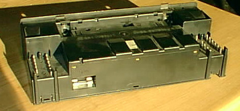
CLIMATE
CONTROL PUSHBUTTON UNIT (added November 2010)
The pushbutton unit has the circuitry that
tells everything else what to do. It
tells the switchover valves to open and close various ports (which control the
various flaps and vents) based on the pushbutton and wheel settings as well as
the sensor data (ie interior temp sensor, feedback
potentiometer, evaporator temp sensor, compressor speed sensor, etc) and it
also controls the function of the air conditioner compressor. On our unit, we replaced it when the temp
wheel spun round and round. Obviously
its ability to set the proper temperature is hindered when this happens. Also, the pushbutton contacts can become
dirty, and a
shot of contact cleaner can go a long way towards restoring functionality. Also, it has been reported that the pins on
top of the control unit, as well as the corresponding plugs on the harness, can
become dirty (see photo below).
Electrical contact cleaner should also be used on both of these areas. The circuit cards inside these units are
also subject to hairline cracks over time, and if you are so inclined, you may
want to look the circuit card
over with a loupe to see if you can find the broken
connection.
George Murphy at Performance Analysis in
If you find your unit needs replacing, beware
of just buying a replacement on eBay.
The electronics changed over the model years, mostly in their ability to
control the compressor, and they are not interchangeable. My car, a 1985, calls for a unit numbered
201 830 03 85. Interestingly enough, the unit I took out
of my car was a 201 830 05 85,
but best to use the correct number. It
is possible that these two numbers are considered interchangeable.
201
HEATER CORE - KABOOM! (added November 2010)
So I was driving home from work one night and
then I received The Call from Mrs C - car full of steam, a loud noise, carpets
soaked with hot coolant, blue jeans too.
She quickly pulled over and got out.
I arrived at just about the same time as the AAA tow truck, who brought
it home to our garage. By the time I was
home, I had worked out in my head what had happened - a catastrophic failure of
the heater core. As I found out later,
one of the plastic tanks along the side had cracked (see below). And I knew what I had to do: dash removal, heater box removal, heater box
disassembly, and then put it all back together, but not before changing out
some parts which it would be wise to replace now that the tough parts to get at
can be accessed easily - specifically, the feedback potentiometer, its
accompanying vacuum element, and the fresh air flap vacuum element. The other two vacuum elements should also be
changed if more than ten years old - mine were about two years old, so I kept
them. Dash, heater box and heater core
removal instructions below towards the bottom.
Photo below shows exactly where the heat exchanger cratered. Some people believe that failures such as
this can be caused by using green coolant instead of Mercedes-Benz brand
coolant. Why take the chance? Always use MB coolant. It is no more expensive than other coolant.
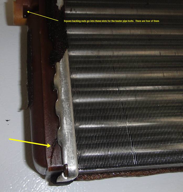
When removing the heater box from the car, I had a panicked
moment when some square nuts came tumbling out onto the carpets, and I had no
idea where they came from. They were
square - very un-Mercedes - but I put them aside anyways. Mystery was solved a short time later when I
found out four of them were used to secure the two pipes to the heater
core. New nuts and bolts come with the
heater core but I don't like the new bolts.
More on that below.
INTERIOR
CABIN TEMPERATURE SENSOR
This is a great place to start. If this sensor is not working properly, there
is no way the system will work right. It
is located right next to the rear view mirror, and we are going to test it and
clean it of all the gunk and smoke that has blown through it all these
years. It has a two-wire plug and a hose
attached to it. The hose goes down to
the aspirator blower, and we will test that below. Pry out the light next to the rear view
mirror, and on my 1985 the way to remove the sensor is to reach in and slide
the U-shaped clip holding it in position towards the driver side. Once the clip is out, then the small plastic
grille can be carefully pried out, freeing the sensor. Now test it with an ohmmeter. 68F should yield 11.5 to 13.5k ohms, 77F
should yield 9.5k-10.5k, 86F should yield 7.5-8.5k ohms. Also, take a look inside the hole, and give
it a few blasts with some electrical contact cleaner. Now test again with the meter. To reassemble, push on the wire and the
hose, and line up the sensor business end with the opening in the headliner and
push the plastic grille into place. Then
secure with the U-shaped clip and replace the dome lamp.
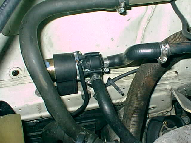 INTERMITTENT BLOWER?
If you find that your blower is working
intermittently, in the heat mode, it is a good chance that your auxiliary water
pump mounted on the inside fender well below the radiator bottle (see photo) is
old and/or broken and drawing too much current. This causes the ACC system to
shut down. To test for this condition, unplug the aux pump (a 2 pole connector
that clips next to the pump bracket) and see if the blower begins to function
normally. If this is the problem, then keep the pump unplugged until you are
able to replace it. If this is not done, the malfunctioning pump can damage the
IC's on the pushbutton unit. The aux pump is not a critical item; it only
serves to keep the hot water running through the heater core during heavy
traffic or when the engine is otherwise idling. I paid $118 for my replacement.
However, I replaced mine when it started to leak.
Sometimes you may experience a blown blower
fuse. Mercedes-Benz had a recall on some of the 190's, and it had to do with
the fact that some blowers needed more current than the fuse could handle. The
fix is to install a fuse bridge. If your fuse keeps blowing, call Mercedes-Benz
at their 800 roadside assistance number, and they will direct you to someone
who can look up online whether your car requires this service, and if it has
been done already.
 TOO MUCH AIR CONDITIONING?
Sometimes the compressor just won't shut off
while the system is operating. The first place to check is the fuse on the back
of the pushbutton unit. I provide detailed instructions below for removal of
this device. See the photo below for the exact location of this fuse.
TROUBLESHOOTING THE HEATER VALVE
If your symptom is too much heat, a
good place to start is the heater valve located under the leaf trap between the
2 firewalls on the passenger side, just behind the battery. It is a simple
vacuum-operated element which controls a gate that, when vacuum is applied,
shuts off the coolant flow on the return pipe of the heater box. Siphon off
some coolant, remove the black "leaf trap" that sits just underneath
the windshield, and find the valve. Pull off the vacuum pipe from its top,
loosen the 2 hoses from either side, and remove it. Check it for smooth
operation, and finally put the vacuum pump onto the element and see if it holds
the vacuum. If it doesn't, it's a $25 part. It might be a good idea to replace
it anyway; some owners have noticed that over time, the valve leaks a small
amount of coolant. Also, this valve can
fail internally, although the vacuum part is ok. This will keep the heat out of the car until
the problem can be completely diagnosed and rectified. If it is in the middle of summer and your
only concern is keeping heat out of your car, you can either apply vacuum
directly to the valve, thus keeping it closed, or you can bypass it entirely by
either blocking the flow somehow, or else run the hose in such a way that it
bypasses the heater core entirely. So,
in summary, no vacuum=full heat, vacuum=closed.
So, now that you have access to the valve,
check for proper vacuum going into the valve by plugging your vacuum pump
directly onto the dark red pipe which fits onto the heater valve. Start the car and set the system to maximum
cold. Is there vacuum present? There should be, and if there isn't, then it's
time to dig deeper into the system.
Best to check the integrity of the pipe from the switchover valves., and be aware that there is a 2" rubber hose
joining the 2 pieces of dark red pipe between the heater valve and the
switchover valve.
CHECKING FOR VACUUM LEAKS
The center of the whole system are the
switchover valves. There are two of them, and all of the Tempmatic
vacuum pipes connected to the vacuum elements terminate at either one or the
other. This makes it an ideal spot to quickly check the whole system for vacuum
leaks, which can occur due to heat or age.
Accessing the switchover valves is done by
removing the glove box, the right hand side vent, and the aspirator blower, in
that order. To remove the glove box, first pull out and unhook the small clear
rectangular light. Along the edge of the box are seven black 2-piece plugs
which hold the box in place and can be pried up, one part at a time. The box
then comes out. The right side air vent is removed by grabbing on to the grille
with a pair of needle nose pliers wrapped in a rag. Give it a tug, and it comes
right out. The frame comes out once the four plastic prongs behind the grill
are pried slightly away, allowing it to be pulled towards you. You may find
that the frame comes out easier if you work at it from behind by removing the
stereo speaker just above it.
Now we test and remove the aspirator blower.
It is cylindrical, and sits directly behind the right air vent. Its function is
to suck air past the interior air temperature sensor located in the headliner,
thus facilitating a quick response from the ACC system. If the symptom of your
system is a slow response time, this is a good place to check. There are two
ways to test the aspirator blower. The first way it to turn the key on, and
light a match in the car. Blow it out, and put the smoking match up to the
sensor, in the headliner. Does the smoke get drawn in? Then it's ok. Or, you
can also turn on the ignition and hear it run and see the fan blades spinning.
Also, sometimes the pipe leading from the blower to the sensor can disintegrate
due to age, so make sure it's in one piece. (Try blowing through it.) Once
you've checked it all out, take it out by lifting it up from its securing clip,
and unplugging the electrical connector. Work the pipe loose, and take the
blower out.
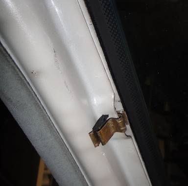
Now we maneuver the two switchover valves
into a more convenient spot for testing purposes. They clip into place to the
black bar in two places, and on my car they were also secured by means of a
black nylon tie. Cut the tie, unclip the valves, and gently take them out of
the glove box, leaving them connected.
Finally, time to begin the vacuum leak
testing process. Here is a vacuum diagram to help you understand the flow:
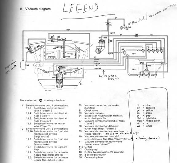
Testing for proper engine vacuum - Notice
that vacuum comes from the manifold (or vacuum pump in the 190D) to both
switchover valve inputs through a rubber Y. There should always be vacuum at
this Y, as long as the engine is running. So let's test to see if it's still
the case. Separate the pipe from the Y, and plug the pipe into your vacuum
pump. Start the engine. Vacuum ok? If not, look for a vacuum leak between the Y
and the manifold. When done, put it all back together. Switch off the engine. A
good place to start is at the rubber hose that joins two pieces of pipe between
the manifold / vacuum pump and the Y at the switchover valve.
Now we can test the pipes and associated
elements on the 4 port switchover valve. In the MB ACC Tempmatic
book this device is known as #11.
Port 5, on the left, has a dark red pipe, and
goes to the heater valve element. Pull the pipe off the switchover valve, put
the pipe on your vacuum pump, draw it down and see if it holds vacuum. If not,
follow the line and find the leak. It's a good practice to use a new rubber
elbow to connect the pipe to the switchover valve. These parts are cheap and
can prevent vacuum leaks later.
Ports 4 and 3, next to it, control vacuum to
the blend air flap element. Note that they are connected together with a rubber
Y. Port 4 supplies vacuum when cold is selected, and port 3 vents to atmosphere
when more heat is needed. The switchover valve receives its instructions from
the pushbutton unit. To test, remove the green pipe from the Y, and plug it
into the vacuum pump. Apply vacuum and see if it holds. If not, you need to
find the leak. It may be a bad element on top of the heater box, or a bad
rubber elbow on the element. You may need to remove the dashboard to trace the
leak unfortunately. Reassemble the Y when done.
Now we test the pipes and elements connected
to the 5 port switchover valve. In the ACC manual this device is known as #12.
Ports 10 and 9 both go to the fresh
air/recirculating flap underneath the heater case. Unplug each in turn and
connect to the vacuum pump. See if they both hold vacuum. They should. It is a
2 stage element, meaning that one pipe is for a short stroke and the other pipe
is for the long stroke.
Port 8 has a middle green / white pipe which goes
to the legroom flaps element underneath the heater case but above the fresh air
vacuum element. Remove the pipe, plug it into the vacuum pump and see if it
holds vacuum. It should.
Ports 7 and 6, on the right side of the #12
switchover valve, both go to the defroster outlet flaps element on the left
side of the heater case. This is another 2 stage element, and both should hold
vacuum.
REMOVING THE LEGROOM FLAP AND FRESH AIR /
RECIRCULATING AIR VACUUM ELEMENTS
If you find that a vacuum element is no longer
holding vacuum, you may elect to repair the old one, or just purchase a new
one. George M. sells the rubber inserts, along with instructions on how to
change them. It does not take long once the elements are out of the car.
Both the legroom flaps element and the fresh
air / recirculating air element are located behind the radio, but the center
console must come out first. It sounds more difficult than it is; first remove
the center vents using a needlenose pliers surrounded
by a rag, and then, after closing the vents first, remove the two screws
holding it up to the dash. Use an offset
screwdriver for this, or you can also use short screwdriver sockets. Then remove the two screws holding it to the
transmission tunnel on either side. Remove the panel under the steering wheel,
and then the whole unit should just move forward. Unplug the connectors to the
rocker switch, the fan switch, the two pushbutton unit connectors, the two
ashtray connectors, and anything else you see in the way, including the radio.
Move the center console out of the way so you can get to the two elements. It
is easy to remove the elements once you know the trick.
The legroom flap one needs to come out first.
The secret is that they don't just turn out. With a flashlight, look at the
bottom of the element where the bayonet-style fitting sits in the metal
bracket. One of the three bayonet catches is longer than the others, and the
extra length is a piece of flexible plastic which pops into a hole in the metal
bracket once the element is oriented correctly. This little plastic button
keeps the element from twisting or shaking out of the bracket. Knowing this,
the easiest way to remove the element is to locate the plastic button sticking
up, push it in, and turn the element out. Pull up on it the whole time to help
the button out of the hole. Once it is out of its bracket, remove the plastic
cover over the end of the actuator rod. Using a small screwdriver, gently pry
towards you the metal rod going to the legroom flaps. The actuator rod should
then just come out. Maneuver the element out of the car.
The fresh air flap element secures to its
bracket in the same way. The bad news is that the plastic button is on the
hardest to access part of the bracket. I was able to push the little button in
with my finger and pull up with the other hand. Remove the two vacuum pipes,
noting that the green/yellow pipe is on top. The actuator rod is held into the
door by a small plastic fitting. Give it a quick push and it should pop out. Once both elements were out, the first thing
I did was to file down the button to half its size so that next time they would
come out without having to worry about finding the buttons. I found that it is a good idea to test and
visually confirm proper operation of the vacuum elements before putting the
center console back into place. It is
possible to hook up all the cables and then just not screw it up into place and
watch the elements open and close as the various buttons are pressed.
THE
DEFROSTER VENT VACUUM ELEMENT
First of all, what is the function of this
part? If you were to remove the
steering wheel and instrument cluster and watch it work (and this is what I
did), this is what it would do: if you select one of the console buttons that
points air towards the windshield, the element should move in one direction,
and vice versa. All this does is route
the air up or down. You can troubleshoot
the defroster vacuum element a couple of different ways. Firstly, if you have access to the switchover
valves, see if both parts of it are holding vacuum. If not, then the rubber element has
failed. You can also check it by
removing the instrument cluster and viewing its operation as indicated
above.
If you determine that the defroster vacuum
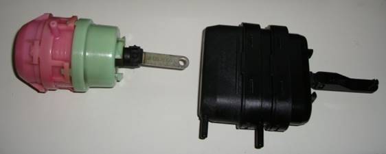
element is bad, the first step is to get a replacement element. Note that there are two different varieties
of vacuum element (see photo below). The
pink and green one is the earlier version, part number 201 800 05 75, and the
black flat oval one is the later version, part number 000 800 87 75. The later one is not a replacement for the
earlier one, so if you need the earlier one, don’t buy the later one and expect
it to fit. In my particular case, I
found that the VIN cutoff number wasn’t accurate; Mercedes claims I needed the
newer style, while only the earlier style with the round bayonet mount will fit
in the car. See the photo below of the
two varieties.
To change it, remove the steering wheel
(caution if your car has an airbag) and then the instrument cluster. In order to remove the instrument cluster, it
is first necessary to unhook the speedometer cable, and that isn’t always so
easy. Try sliding out the cluster an
inch or two and then try to slide your hand back there and unscrew it. It is easier to unscrew it than to screw it
back on. I found the easiest way to
screw it back on when the time comes is to remove the bottom panel by the
pedals, and then work your hand up and behind the cluster. A bit of grease on the cable and threads
helps a lot, and also line up the cable with the speedo before giving the
cluster a push into a closer position.
OK, so once the steering wheel and instrument cluster are out of the
way, the rest is easy. Look straight
ahead and you can’t miss it. Remove the
element, taking care not to lose the little white plastic connector that fits
on the end of the rod, and turn it out while prying it slightly away from the
mount to override the little plastic button which prevents it from unscrewing
on its own. As long as you are at it,
replace the rubber vacuum pieces which connect the elements to the tubes. If they are old, they can crack or lose their
elasticity and create vacuum leaks of their own
TESTING THE SWITCHOVER VALVES
The switchover valves consist of several
small vacuum elements which open and close via separate electrical contacts
upon the command from the pushbutton unit, which gets its command from various
electronic sensors. Switchover valves can fail electrically as well as
mechanically. Judging by the fact that Fletcher Jones had 3 of the new-style
switchover valves in stock when I called (more on the new-style switchover
valves later), I'd bet that they replace these things quite regularly.
Now, this time around, instead of testing the
pipes, we will test the ports to see if they are providing proper vacuum. Note
that if a fault is detected here, it does not necessarily mean that the
switchover valves are bad, although the part does become suspect. Starting with
the forward switchover valve, the 4 port, #11:
Let's go back to port 5, on the front 4-port.
Remove the dark red pipe, and plug your vacuum pump onto the port. Start the
car, and turn the temp wheel to Min, meaning maximum cold. Your gauge should
register vacuum, as this will close the heater valve. If this doesn't happen,
make a note of it and put the pipe back on. Below is a picture of the new style
switchover valve, courtesy of James Meyers. Notice how all the ports on the
other two valves are incorporated into this single unit.
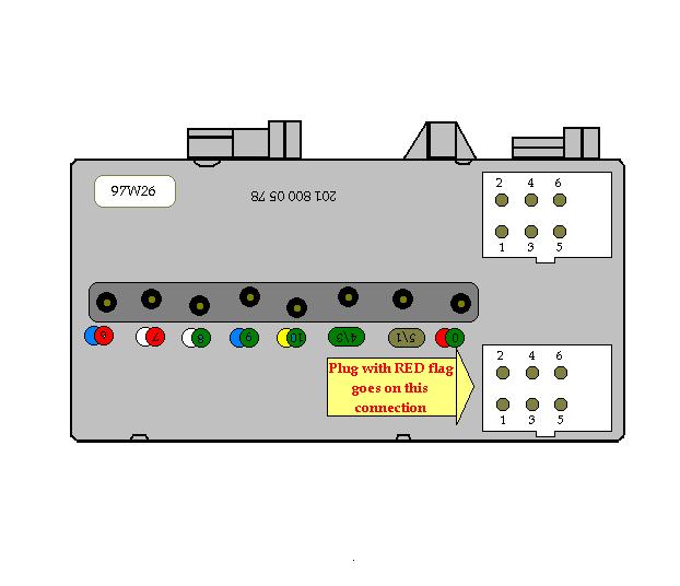
And also, courtesy of James, is a diagram of
how to plug in the two identical connectors. There are no markings on the
switchover valve, so this picture will tell you how to do it.
THE DREADED 190 CLICKING BEHIND THE GLOVE
BOX NOISE
Ports 4 and 3 as mentioned earlier work
together to alternately supply and vent vacuum to control the blend air flaps
to regulate temperature. This is the source of the clicking behind the glove
box which has plagued so many of us 190 owners, as the system electronics
rapidly try to set the blend air flaps to the correct spot. This noise is not
indicative of a bad switchover valve, however. It is much more likely that the
associated electronics are faulty, but I will elaborate more on this below. To
test the switchover valve, remove the Y from port 4, and see if vacuum is
present at the port after setting the AC to maximum cold. If it's ok, then plug
the gauge into port 3, and set the temp to cold. Pump in some vacuum. It should
hold. Then swing the temp dial to max heat, and see if the vacuum is vented as
the blend air flaps move accordingly. If this doesn't happen, make a note and
put it back together.

On my car, I noticed that ports 4 and 3
became very hot once upon a time, as there was burn marks surrounding the area
where the pipes plug in. Nothing concrete in that, but very suspicious!
Now let's test the rear switchover valve, the
5-port. Select maximum heat and start the car:
Ports 9 and 10 should receive vacuum when the
"0" is selected;
Port 8 should receive vacuum when the third
from left button (2 white arrows) is selected;
Ports 7 and 6 should receive vacuum when the
second from right (center vent) button is selected.
The electrical portion of the switchover
valves can also be tested, but the ACC manual shows how to do it from the
pushbutton unit connectors. It's a good idea to do it this way, as removing and
then plugging in the connectors sometimes has the ability to restore a dirty
connection. You may even want to spray the contacts with electrical contact
cleaner.
To access the pushbutton unit connectors, we
first need to drop the center console. Remove the two center vents using a rag
and needlenose pliers, and then loosen the two
Phillips screws holding the console up to the dash. Close the vent so you don't
lose a screw into the console. Once the screws are out, the whole unit pivots
down a couple of inches, and the 2 plugs are clearly visible on either side on
the back of the pushbutton unit.
To test the 4-port switchover valve in front,
we check for the presence of a short or open circuit, and it is done from the
left hand connector at the pushbutton unit. There should be 60 - 70 ohms
between contacts. Remove the left side connector. Connect the negative ohmmeter
probe to a good ground (there's a metal nut in the area) ,
and test holes 1, 2, and 4 for either a short or an open circuit, which would
indicate a definite problem with that part. (ACC manual, pp. 83.11-039/3)
The 5-port switchover valve can be checked by
using the pushbutton unit right hand connector. With the valve plugged in,
connect the negative ohmmeter probe to a good ground, and test holes 1, 2, 3,
5, and 6 for either a short or an open circuit, which would indicate a problem
with that part. (ACC manual, pp. 83.11-039/4)
The good news is that if you determine that
your switchover valves are not functioning properly, whether there is an
electrical problem and / or the vacuum doesn't seem to be routing properly,
Mercedes-Benz has redesigned the two parts into one unit. This simpler design
does not require the use of the two rubber Y's, and thus there are less parts
to leak vacuum. I have also noticed that they do not click quite as loud. I
would imagine it is also more reliable on the inside too.
TESTING THE FEEDBACK POTENTIOMETER
 The final component this article will test is the
feedback potentiometer, which is an electronic device that lets the pushbutton
electrical control unit know exactly where the blend air flaps are. Part number
for the 1984 and 1985 cars is A 2018210260.
I do not know if the part changes for later cars. It may not.
Like any electromechanical device, this component is prone to wearing
out, getting dirty contacts, or going out of adjustment.
The final component this article will test is the
feedback potentiometer, which is an electronic device that lets the pushbutton
electrical control unit know exactly where the blend air flaps are. Part number
for the 1984 and 1985 cars is A 2018210260.
I do not know if the part changes for later cars. It may not.
Like any electromechanical device, this component is prone to wearing
out, getting dirty contacts, or going out of adjustment.
It is difficult to access, but can be tested
via its wires from within the glove box. Locate the 3 wire connector which can
be found in the dash around the right side of the center vents. Pierce the
center green and red wire with the + probe of your voltmeter, and secure the
other one to a GOOD ground. A bad ground wire will yield lower and inaccurate
voltage readings., so make sure you've got it right.
(My first attempt at adjusting my potentiometer was thwarted by a bad ground.)
Start the engine, select the button for the center air vents, and set the temp
wheel to the minimum, meaning maximum cold. You should read 4.4 - 4.5 DC volts
for cars up to 1986, and 2.4 - 2.7 volts for cars 1987 on. Turn the temp dial
back and forth, and watch the digital readout. If at any time there is an open
circuit, then the the pot is bad. If the readout is
in any way less than perfectly smooth, then it is dirty or defective. Any
problem in this area is more than likely going to result in the clicking noise
over at the switchover valve #11 as the erratic electronic readings give the
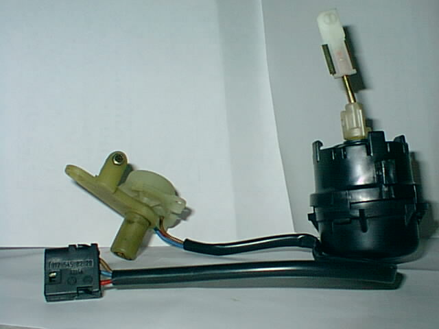
vacuum elements mixed and confusing signals. The picture below shows the
feedback potentiometer along with the associated vacuum element.
The vacuum element shown in the photo is an
example of one way the part can go bad; note how the metal rod can flex to one
side and can no longer accurately control the feedback potentiometer. The
rubber in the element can also disintegrate due to heat or age.
If the feedback potentiometer is out of the
car, an ohmmeter is a good way to test how well it operates. Smooth readings across the range is key. In the photo below, I opened it up by
carefully prying the three plastic tabs.
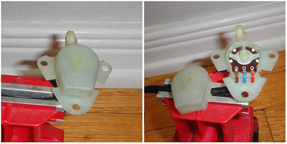
The cover lifted off to reveal the pot. I
gave it a good spray of electrical contact cleaner, and then measured the
resistance across the three wires, two at a time, when the lever is at the far
left, and again when it is at the far right.
Resistance ranges were as follows:
Red
and blue: 1k - 5k ohms
Blue
and brown: 11 ohms to 4.2 - 4.7k ohms
Brown
and red: 5k - 5k ohms
Your
readings should be similar, although probably not exactly like mine, and
remember smooth across the scale. Keep
in mind that the movement range of the lever is adjusted with a screwdriver
once it is in place on the heater box. See the voltages listed above in the
Testing section. A non-digital voltmeter
may work better to measure smoothness.
On a digital meter, I had better results going from high to low.
By
the way, this test can also be done while the pot is still in the car. The lever is controlled by a vacuum element;
disconnect the top of the ‘T’ on switchover valve ports 3 and 4. Using a Mityvac, slowly suck the air
out. This should move the feedback
potentiometer through its range.
The
pot looks pretty basic; if you were in a pinch, I bet you could take the pot
out of this housing, find a similar one on eBay, and put it back together.
If there is a problem with your feedback
potentiometer, it will be necessary to remove the dashboard, steering wheel,
and instrument cluster in order to change it. It is a time consuming job, but
not an overwhelming one if taken step by step. The good news is that it is a
good opportunity to change that cracked console. New dashboards can be had for
about $350 or so. Give yourself about a
week for good measure to take your time and do it right. Figure a day to get the dash off, a few days
to get the parts (once you know what you need), and then a day or two to get it
all back together. The 201 chassis
manual gives thorough instructions on how to do this step-by-step. It is not
difficult but takes a while. Also, see
my take on how to get it off below.
If your system seems to be getting erratic or
erroneous signals, the switchover valves just are not doing what they should,
and your feedback potentiometer checks out OK, your problem may be in the
pushbutton unit. Frequently they develop cracks in the printed circuit boards.
You may be able to determine if this is your situation by removing the box and
also the bottom. The plug it back in, and turn on the system. See if you can
get different things to happen to the ACC system while you are gently flexing
the PC board with your fingers. If this happens, then you may be able to spot
the loose solder joint which can be resoldered with a
low voltage soldering iron and some rosin core solder. Alternatively, George
Murphy can test these units inexpensively, and if there's a problem with it, he
sells rebuilt exchange units.
NOVEMBER
2010 - DASH REMOVAL - Not difficult,
but lots of little projects and parts, so get organized. My method is to have a box of ziplock bags handy, along with some Post-It Notes. All screws in each 'project' get put in a
bag with a note. Here we go:
Steering Wheel - Non airbag cars: pry out the
center logo, using a small screwdriver.
See the big allen
bolt in the center? Mark the wheel and
steering rack with a sharpie pen so you can line the two up once the wheel goes
back on. Using a big allen
socket on a eighteen inch breaker bar, or longer, remove the bolt holding the
wheel in place. Give it a really big
'snap'. If you try gradual pressure, you
will never get it out. Just one big fast
push should do it. Airbag cars: I have no experience with this. You are on your own. But be careful.
Four air vents - with each one, use a pliers,
protected by a rag, and yank them out.
These get brittle with age and are not expensive if you need to replace
them.
Headlight knob - Using same pliers and rag,
yank off the knob. Undo underlying nut,
and then put plate, knob and nut in a baggie.
Bottom panels - Remove screws holding them up
from under the instrument console and glove box. Easy.
Ignition trim ring - Pry off using a small
screwdriver. Piece of cake.
Steering column surround - Once the steering
wheel is off, there are some bolts surrounding the big bolt which should come
out. Then the turn signal switch and
cruise control switch should be removed.
They can be left hanging in place.
I did this because the first time I removed the dash, I inadvertently
destroyed the cruise control switch as I wrestled it into place. Not again.
Glove box: Using a small screwdriver,
separate the two little plastic grommets that go around the inside of the glove
box. Take out the top bit, then pry out
the bottom bit. Then pry out the little
light and disconnect. Unscrew the two
screws holding the latch in place.
Everything in the baggie. Slide out the box.
Dash speakers - remove the two small screws
holding the covers in place. Then
unscrew the speakers, remove the wires.
See those bolts in each side?
They hold the dash in place. We
will get to them later.
Drivers side vent fascia - Carefully pry out
the little switch for the interior light.
Unplug. Then carefully pry up on
the four plastic tangs holding the part into the dash. Remove.
Center console - Using an offset or really
short screwdriver, remove the two small screws in the center vent fascia
holding it up. Then remove the two
screws below, on either side. Drop the console down, and disconnect the two multipin connectors on the climate control unit. Unplug the connector on the fan switch. Unplug the radio connections. Then take the whole thing out of the car.
Center vent fascia - See photo below. Using an appropriate allen wrench, loosen the bolt on the little lever
which secures it to the heater box. Pry
out the switches, and then remove the two additional upper screws holding it in
place. Remove.

Instrument cluster - this is the part which
is hardest. Step 1 is to unhook the
speedo cable. Carefully pry out the
cluster, and try to get the cable off either by going in through the side, or
by going up from below. It is possible
to gain a little more space behind the instrument cluster by first unmounting
the headlight switch and using that space to jam your hand in. Then unscrew the knurled nut, and once this
is done, it comes out a little more.
Snap a photo of the different wires, and where they go.
Pillar panels - with the front door open,
pull back the weather stripping around the pillars going from the roof down
along the windshield to the dash.
Carefully work them off. They are
held in place by clips. Once removed,
put the weatherstripping temporarily back in
place. As you can see in the photo
below, the pillar needs to be pulled straight back. The clip in the picture below contains the
plastic remnants of my pillar panel which was undoubtedly caused by pulling the
panel in the wrong direction. Next time
it will go better.
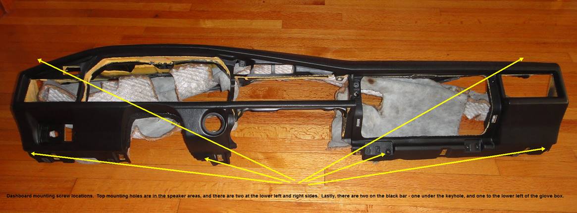
The dash - Remove the bolt on the far left
and far right side. On the left side, it
is near the headlight switch. Remove the
two bolts in the front speaker areas, and then remove bolt holding dash below
glove box. Also one more on underside holding
it to the big black bar, just below keyhole.
At this point, it should just lift out.
DASHBOARD
REINSTALLATION - Fairly
straightforward, but there are a few things to keep in mind. I ended up doing everything exactly twice -
a part would go on, something would not be right, and off it would come and
then I put it back on. Whenever this
happened, I made note of it, and I write about it below.
Probably best to replace the two foam square
surrounds on the top of the heater box.
In Mercedes-eze, these are called a 'Sealing
Rubber Joint', part # A 201 835 00 98.
My two replacements had to be ordered from
I found it easiest to put the dash into place
first, and then loosely secure it with the two side bolts. Then I put in the top speaker bolts, and
lastly the two on the lower edge at the key and glove box. Organize the wires by pulling all instrument
cluster wires out through the cluster opening.
Organize the fiber optic wires. The function of the fiber optic wires is to
supply lighting to the three center vent fascia switches as well as the rear
cabin light switch to the left of the instrument cluster. The light source comes from bulbs in the
instrument cluster. A good idea to
change these bulbs as long as they are accessible. They are cheap and don't last forever.
Glove box - try trimming back some of the
insulation padding. It makes it fit a
little easier. Also, before you close it
up, make sure all the pipes are securely on the switchover valve ports. I had to take mine out again because one
popped off, and I only found this out after everything was back together.
Center Vent Fascia - This was the first item
I reinstalled. Before you install it,
make sure there are clips on the dash holes so the two screws have something to
grab onto. Do not tighten the center allen bolt too tight, as this
would keep the vent from opening. Keep
trying the vent as you tighten to get it just right. Make sure the clips are on the dashboard
holes. Mine was almost completely
installed before I discovered this. Had
to take it off again.
Center console - don't forget to plug in the
cigarette lighter power plug and the little light for the ashtray.
Instrument cluster - Above I wrote about how
to get the speedo cable off the cluster.
Upon reinstallation, I had another problem - they 'key' broke off the
big round multipin connector. I was then stuck with the task of orienting
the plug correctly. Using my ohmmeter, I
found the pin that controls the instrument lighting by measuring resistance and
turning the light dimmer rheostat. The
corresponding pin on the plug (from the Electrical Troubleshooting Manual) was
#13. I then lined the two up and I was
over that hurdle. Put a little grease
on the threads of the speedo cable. It
makes it go on just a little bit easier.
After putting it all back together, I tested
the system, and something wasn't quite right.
With the ac off (if bottom button pressed), the up arrow button worked
ok through the hot and cold, but the two up arrow buttons only gave me hot air
in the defroster vents. So I then
pressed the center vent button, opened the center vent, and I had a mixture of
hot and cold. I turned on the ac and
still had a center vent mixture of hot and cold. So I took the glovebox out again, and lo and
behold, the pipe had come off port #8.
While port 8 is for the legroom flaps, and the system should work fine
without legroom flaps, it is the vacuum leak which caused the problem. The same result could also come from a torn
legroom flap vacuum element. Or any of
the elements. So always best to get out
your mityvac and take a look at those switchover
valves and make sure everything is connected and tight.
HEATER
BOX REMOVAL - The good thing about
removing your own
heater box is that once it is out, you can take a little time and
give it its first real cleaning in 20+ years.
It comes apart easily, and all the accumulated smoke, dust, grime, etc
can be cleaned from the flaps and passageways.
Removal of the dash is the first step.
You should know that coolant goes into the heater core from the engine
on the left side and then goes back to the engine on the right side. The core, even though broken, may or may not
be full of coolant at this point, so just be aware of that.
Plumbing - The manual calls for removing the
pipes first from the engine as well as a white retaining clip; however, I found
that my heater core came out once I removed the two pipes on either side of the
core (two bolts each, and then gently pry out the pipes). The white retaining clip comes out by gently
working a small screwdriver underneath each of the little plastic bits that go
into the holes. I broke mine attempting
to get it out, and wouldn't you know it, the part is no longer available from
Mercedes. So be gentle with it. Also, as noted above in the photo of my
cracked heater core, there are four square backing nuts which secure the heater
pipe bolts into place. New ones came
with my heater core.
Cable Tie - Using a pliers, squeeze the black
cable tie on the left side of the box.
Open the tie so the wires can come out.
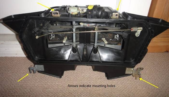
Bolts - The heater box is held in place by
four bolts. Two are at the very top, and
the other two are one the sides. On the
left side, it is next to where the pipe goes through the firewall. The manual calls for just loosening this
bolt, as the box slides up and out, but the box comes out easier if the nuts
are removed. There is a similar looking
bracket and bolt on the right hand side.
Remove this bolt too. Pry off
the little plastic clip on the hose on the drivers
side. (see the
lower right arrow below). This clip
press fits into the two little holes. It
is brittle, so beware.
Lower Vacuum lines - Underneath, remove the
vacuum lines from the vacuum element closest to you. The one farthest back (fresh air /
recirculation flap) does not need to be disconnected.
Defroster Flaps Element - Remove the vacuum
line supplying vacuum to the defroster elements.
Feedback potentiometer - On top of the case,
remove the vacuum line controlling the feedback potentiometer. Also unplug the connector (see photo above of
feedback potentiometer and vacuum element).
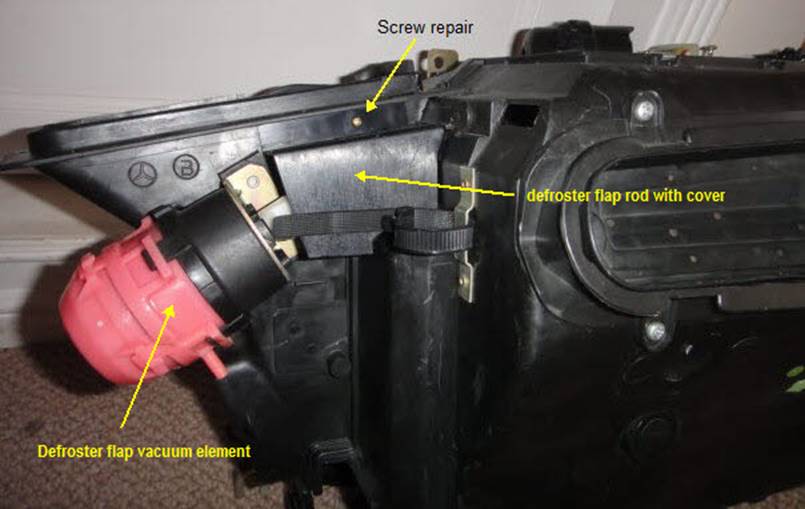
HEATER
CORE REMOVAL - Once the heater box if
out of the car, heater core removal is not difficult.
Remove the defroster flap rod - See photo
below of the other side of the box.
CAREFULLY bend the plastic cover upwards - it will break if you use too
much force, and then you have to repair it like I did - and remove the little
plastic rivet holding the element to the rod.
Then pull out the rod from the defroster flaps.
Remove the lower legroom nozzles. Be careful not to rotate the nozzles on the
rod, as this may put it out of adjustment.
Remove all the little silver clips holding
the two halves together. Separate the
two halves, and then remove the screws holding the heater core frame into
place. Note the position of the strips which are stuck into
place and will need to be added to the new core.
Now to replace - aftermarket or Mercedes-Benz
original? I was prepared to buy an
aftermarket, but found out that the original Mercedes part (A 002 835 54 01)
was available for just a few bucks more, so I went with that one.
Well, if you are with me this far, you
probably now have a few days to regroup while you are waiting for parts to
arrive. If you are looking for other
projects as long as the dash is out, how about cleaning all the ground points on
the firewall behind the light switch? Many years of corrosion can set in and give
you electrical problems. Better to take
a few moments and get ahead of them as long as they are readily accessible.
HEATER
BOX REINSTALLATION
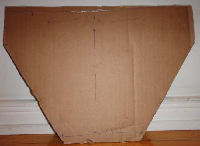
The troubleshooting manual calls for a piece
of cardboard which should be used between the car and the heater box to keep
the rubber condensation tray in place and interfering with the correct seating
of the heater box. Also, before
installation, place the four square nuts into the heater core, and secure them
with a piece of tape. There is no
getting them in once the heater is in place.
Also, before installation, make sure any plugs have been removed from
the heater core. Here is a photo of my
"factory spec" tool:
 "
"
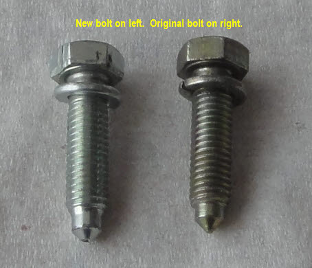
Heater
pipe installation bolts - I found that
the original bolts were more 'pointy' and went in easier than the new
bolts. See photo below. It is a subtle difference, but I spent twenty
minutes and two bruised knuckles trying to get that new bolt in. Finally I switched back to the original bolts,
and thirty seconds later I was done.
There is just not enough of a point on the new ones, and the tips are
too fat to easily line up with the square nuts.
When refilling coolant, it is necessary for
the thermostat to be fully open to fill the heater core, so plan on a drive
around the block, refilling as necessary.
And remember that coolant enters the core from the drivers
side and exits through the passenger side and heater valve.
Finally, if you have found this article helpful, and
you are no longer either freezing cold or boiling hot while driving, you might
consider making a small donation via PayPal to go towards my next martini. Thanks!
![]() PayPalMe/JohnCacavas
PayPalMe/JohnCacavas